Radar System
Akhona Mtshiki
06 October 2025
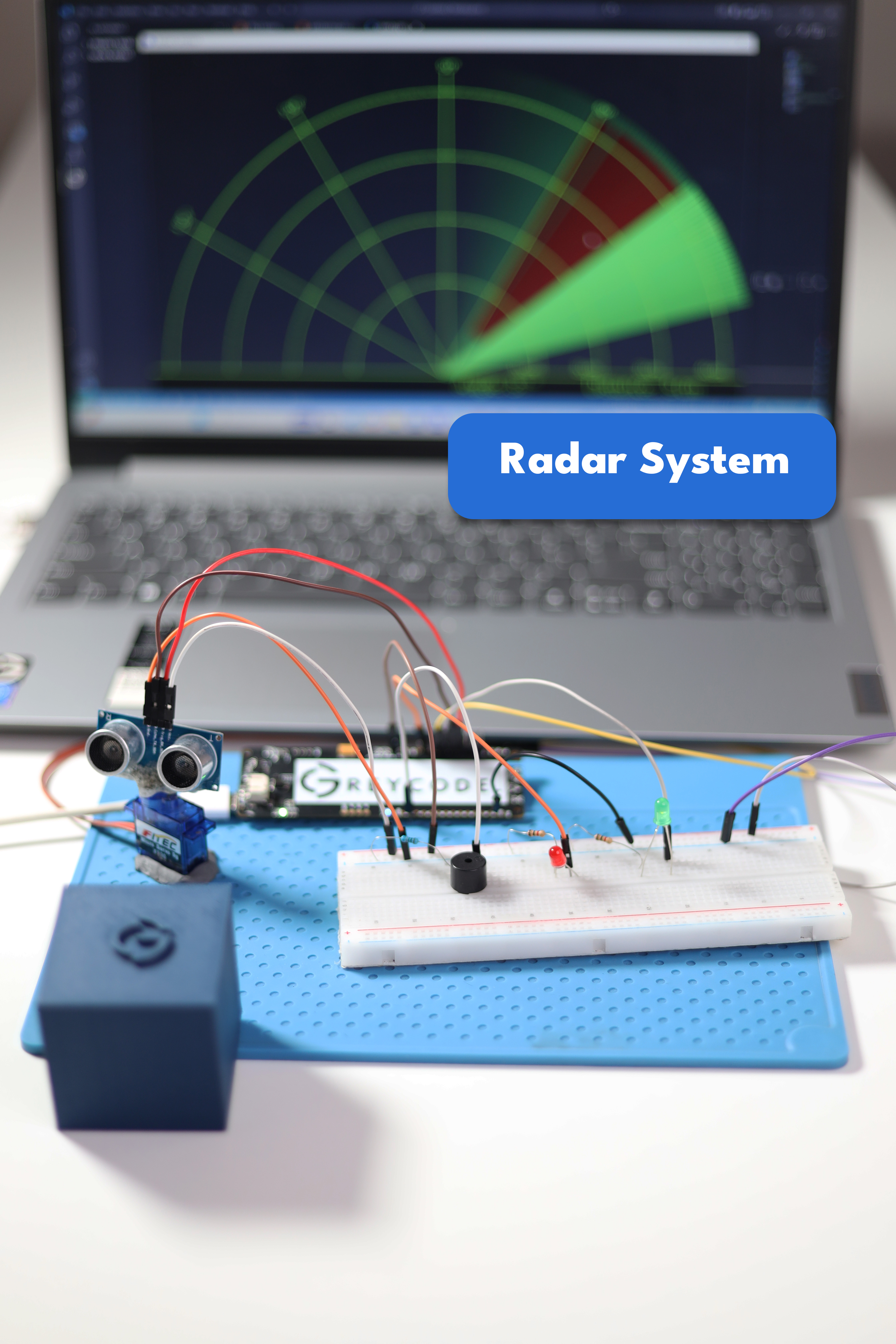
This is a step-by-step tutorial on how to make a beginner radar system using Grecode IoT DevPod and an ultrasonic sensor.
1. Introduction
The radar system turns 0 to 180 degrees with the aid of a micro servo motor. It scans for Objects in the area using an ultrasonic sensor to detect obsticles within 40cm. There are two LEDs and one buzzer installed on the breadboard. The first green LED is turned on when the system is on. It scans around indicating its status. The second red LED flashes only when the radar detects something within range. the flashing speed depends on the distance from the sensor to the detected object. The buzzer acts as an indicator when the sensor detects something within its specific range.
2. Components Required
- Greycode IoT Dev Board
- Ultrasonic Sensor
- Micro Servo Motor
- Active Buzzer
- 2x LED
- Breadboard (Optional)
- Jumper Wires
- 220 Ohms Resistors
- C-type USB Cable (Power Supply)
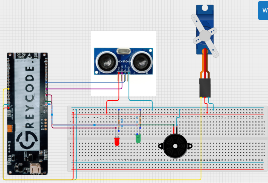
3. Circuit Diagram
Add your circuit diagram image or embed it here.
4. Wiring Guide
Connection between Greycode dev Board and breadboard
- Connect jumper wire from positive on the breadboard to 5V VCC on the Greycode Board.
- Connect the jumper wire to negative on breadboard.
Ultrasonic Sensor
- Connect jumper wire VCC on Ultrasonic to positive side on the breadboard
- Connect jumper wire GND (ground) on Ultrasonic to negative side on breadboard
- Connect jumper wire from Trig_RX_SCL to GPIO 26 on Greycode Board
- Connect jumper wire from Echo_TX_SDA GPIO 33 on Greycode Board
Micro Servo Motor
- Connect jumper wire VCC(red wire) on servo motor to positive side on breadboard.
- Connect jumper wire GND(brown wire) on servo to negative side on the breadboard.
- Connect jumper wire from servo motor to GPIO 5 on Greycode board.
Buzzer
- Positive - GPIO 13 on Greycode board.
- Negative - GND(Ground) on the breadboard
LED's
- Positive - GPIO 14 and 15 respectively on Greycode board.
- Negative - GND(Ground) on the breadboard via 220 Ohms resister
5. Creating a new project in Visual Studio Code (Platform.IO)
To get started with coding your ESP32 Radar project, follow these steps in Visual Studio Code using the PlatformIO extension:
1. Open Visual Studio Code
a. Launch VS Code from your desktop or start menu.
2. Open Platform IO Home
a. On the left sidebar, click the PlatformIO alien icon to open the PlatformIO Home menu.
3. Click "New Project"
a. You'll see a welcome screen. Click the "New Project" button.
4. Enter Project Details
a. Name: Type your project name, e.g. ESP32 Radar System.
b. Board: In the drop-down list, select your ESP32 board (usually "ESP32 Dev Module" under the "espressif32" platform).
c. Framework: Select Arduino.
5. Click "Finish"
a. PlatformIO will now generate a new project folder with all necessary files (like platformio.ini, main.cpp, etc.)
6. Waiting for Indexing
a. VS Code might take a few seconds to install board support and index your libraries. Once done, you're ready to start coding inside the src/main.cpp file.
6. Install Libraries
GREYCODE
GREYCODE SKILLSHARE
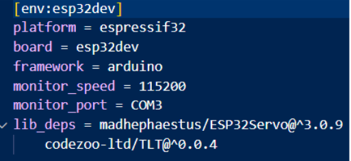
Monitoring speed — you can change it to your choice.
Monitoring_port — plug in the USB cable, then open Device Manager on your computer to see your COM number. Use that COM number here (it enables communication between the Greycode board and Arduino code).
Lib_deps — this is the library you install.
7. Setup
For setting up the radar system we will use two programs — please check the Apps and Platforms section for their download links.
The first program is ESP32, which allows us to send code directly to our Arduino device. After installing the software, create a new Sketch and paste in the script given below. If you followed the wiring image you should be all set! However, if you changed any of the component ports, make sure to also change the variables storing the pin numbers.
After connecting your Arduino to your PC using the USB cable, in the bottom right corner you should see something like "Arduino UNO on COM3". Your COM number will be important later.
We can also monitor the radar's values using a program called Processing, which creates the desired interface for the project. After installation, create a new Sketch and paste in the provided code. There are a few things you will have to change before running it: on Line 18, change the values to your monitor's resolution and set the second parameter to your COM port number found earlier.
After changing everything you're ready to go! In Arduino IDE, click Upload in the top left corner. Wait a few seconds until it sends the code to your device — do not monitor on Arduino IDE. Then go back into Processing and start the program. If everything is done correctly, the green lines in your application and the rotating scanner should be in sync. When an object is detected, red lines will display.
8. Full Functional Radar System Code
Arduino Code
#include
#include

// Defines Trig and Echo pins of the Ultrasonic Sensor, pin of LEDs and buzzer
const int trigPin = 26;
const int echoPin = 33;
const int LEDRED = 15;
const int LEDGREEN = 14;
const int buzzer = 13;

// Variables for the duration and the distance
long duration;
int distance;

Servo myServo; // Creates a servo object for controlling the servo motor

void setup() {
    Serial.begin(115200);
    pinMode(trigPin, OUTPUT); // Sets the trigPin as an Output
    pinMode(echoPin, INPUT); // Sets the echoPin as an Input
    pinMode(LEDRED, OUTPUT); // Sets the LED as an Output
    pinMode(LEDGREEN, OUTPUT); // Sets the LED as an Output
    pinMode(buzzer, OUTPUT); // Sets the buzzer as an Output
    myServo.attach(5); // Defines on which pin is the servo motor attached
}

int calculateDistance() {
    // Function definition
    digitalWrite(trigPin, LOW);
    delayMicroseconds(2);
    digitalWrite(trigPin, HIGH);
    delayMicroseconds(10);
    digitalWrite(trigPin, LOW);
    long duration = pulseIn(echoPin, HIGH);
    int distance = duration * 0.034 / 2;
    if (distance < 30) {
        digitalWrite(buzzer, HIGH);
        digitalWrite(LEDRED, HIGH);
        digitalWrite(LEDGREEN, LOW);
        delay(1000);
        digitalWrite(LEDRED, LOW);
    } else {
        digitalWrite(LEDRED, LOW);
        digitalWrite(LEDGREEN, HIGH);
        digitalWrite(buzzer, LOW);
    }
    return distance;
}

void loop() {
    // rotates the servo motor from 15 to 165 degrees
    for (int i = 15; i <= 165; i++) {
        myServo.write(i);
        delay(30);
        distance = calculateDistance(); // Calls a function for calculating the distance measured by the Ultrasonic sensor for each degree
        Serial.print(i); // Sends the current degree into the Serial Port
        Serial.print(","); // Sends addition character right next to the previous value needed later in the Processing IDE for indexing
        Serial.print(distance); // Sends the distance value into the Serial Port
        Serial.print("."); // Sends addition character right next to the previous value needed later in the Processing IDE for indexing
    }

    // Repeats the previous lines from 165 to 15 degrees
    for (int i = 165; i > 15; i--) {
        myServo.write(i);
        delay(30);
        distance = calculateDistance();
        Serial.print(i);
        Serial.print(",");
        Serial.print(distance);
        Serial.print(".");
    }
}
Processing Code
import processing.serial.*; // imports library for serial communication
import java.awt.event.KeyEvent; // imports library for reading the data from the serial port
import java.io.IOException;

Serial myPort; // defines Object Serial

// defines variables
String angle = "";
String distance = "";
String data = "";
String noObject;
float pixsDistance;
int iAngle, iDistance;
int index1 = 0;
int index2 = 0;
PFont orcFont;

void setup() {
    size(1200, 700); // ***CHANGE THIS TO YOUR SCREEN RESOLUTION***
    smooth();
    myPort = new Serial(this, "COM3", 115200); // starts the serial communication
    myPort.bufferUntil('.'); // reads the data from the serial port up to the character '.'. So actually it reads this: angle,distance.
}

void draw() {
    fill(98, 245, 31);
    // simulating motion blur and slow fade of the moving line
    noStroke();
    fill(0, 4);
    rect(0, 0, width, height - height * 0.065);
    fill(98, 245, 31); // green color
    // calls the functions for drawing the radar
    drawRadar();
    drawLine();
    drawObject();
    drawText();
}

void serialEvent(Serial myPort) { // starts reading data from the Serial Port
    // reads the data from the Serial Port up to the character '.' and puts it into the String variable "data".
    data = myPort.readStringUntil('.');
    data = data.substring(0, data.length() - 1);
    index1 = data.indexOf(","); // find the character ',' and puts it into the variable "index1"
    angle = data.substring(0, index1); // read the data from position "0" to position of the variable index1 or thats the value of the angle the Arduino Board sent into the Serial Port
    distance = data.substring(index1 + 1, data.length()); // read the data from position "index1" to the end of the data pr thats the value of the distance
    // converts the String variables into Integer
    iAngle = int(angle);
    iDistance = int(distance);
}

void drawRadar() {
    pushMatrix();
    translate(width / 2, height - height * 0.074); // moves the starting coordinats to new location
    noFill();
    strokeWeight(2);
    stroke(98, 245, 31);
    // draws the arc lines
    arc(0, 0, (width - width * 0.0625), (width - width * 0.0625), PI, TWO_PI);
    arc(0, 0, (width - width * 0.27), (width - width * 0.27), PI, TWO_PI);
    arc(0, 0, (width - width * 0.479), (width - width * 0.479), PI, TWO_PI);
    arc(0, 0, (width - width * 0.687), (width - width * 0.687), PI, TWO_PI);
    // draws the angle lines
    line(-width / 2, 0, width / 2, 0);
    line(0, 0, (-width / 2) * cos(radians(30)), (-width / 2) * sin(radians(30)));
    line(0, 0, (-width / 2) * cos(radians(60)), (-width / 2) * sin(radians(60)));
    line(0, 0, (-width / 2) * cos(radians(90)), (-width / 2) * sin(radians(90)));
    line(0, 0, (-width / 2) * cos(radians(120)), (-width / 2) * sin(radians(120)));
    line(0, 0, (-width / 2) * cos(radians(150)), (-width / 2) * sin(radians(150)));
    line((-width / 2) * cos(radians(30)), 0, width / 2, 0);
    popMatrix();
}

void drawObject() {
    pushMatrix();
    translate(width / 2, height - height * 0.074); // moves the starting coordinats to new location
    strokeWeight(9);
    stroke(255, 10, 10); // red color
    pixsDistance = iDistance * ((height - height * 0.1666) * 0.025); // covers the distance from the sensor from cm to pixels
    // limiting the range to 40 cms
    if (iDistance < 30) {
        // draws the object according to the angle and the distance
        line(pixsDistance * cos(radians(iAngle)), pixsDistance * sin(radians(iAngle)), (width - width * 0.505) * cos(radians(iAngle)), (width - width * 0.505) * sin(radians(iAngle)));
    }
    popMatrix();
}

void drawLine() {
    pushMatrix();
    strokeWeight(9);
    stroke(30, 250, 60);
    translate(width / 2, height - height * 0.074); // moves the starting coordinats to new location
    line(0, 0, (height - height * 0.12) * cos(radians(iAngle)), -(height - height * 0.12) * sin(radians(iAngle))); // draws the line according to the angle
    popMatrix();
}

void drawText() { // draws the texts on the screen
    pushMatrix();
    if (iDistance > 30) {
        noObject = "Out of Range";
    } else {
        noObject = "In Range";
    }
    fill(0, 0, 0);
    noStroke();
    rect(0, height - height * 0.0648, width, height);
    fill(98, 245, 31);
    textSize(20);
    text("10cm", width - width * 0.3854, height - height * 0.0833);
    text("20cm", width - width * 0.281, height - height * 0.0833);
    text("30cm", width - width * 0.177, height - height * 0.0833);
    text("40cm", width - width * 0.0729, height - height * 0.0833);
    textSize(30);
    text("Angle: " + iAngle + " °", width - width * 0.48, height - height * 0.0277);
    text("Distance: ", width - width * 0.26, height - height * 0.0277);
    if (iDistance < 40) {
        text(" " + iDistance + " cm", width - width * 0.180, height - height * 0.0277);
    }
    textSize(20);
    fill(98, 245, 60);
    translate((width - width * 0.4994) + width / 2 * cos(radians(30)), (height - height * 0.0907) - width / 2 * sin(radians(30)));
    rotate(-radians(-60));
    text("30°", 0, 0);
    resetMatrix();
    translate((width - width * 0.503) + width / 2 * cos(radians(60)), (height - height * 0.0888) - width / 2 * sin(radians(60)));
    rotate(-radians(-30));
    text("60°", 0, 0);
    resetMatrix();
    translate((width - width * 0.507) + width / 2 * cos(radians(90)), (height - height * 0.0833) - width / 2 * sin(radians(90)));
    rotate(radians(0));
    text("90°", 0, 0);
    resetMatrix();
    translate(width - width * 0.513 + width / 2 * cos(radians(120)), (height - height * 0.07129) - width / 2 * sin(radians(120)));
    rotate(radians(-30));
    text("120°", 0, 0);
    resetMatrix();
    translate((width - width * 0.5104) + width / 2 * cos(radians(150)), (height - height * 0.0574) - width / 2 * sin(radians(150)));
    rotate(radians(-60));
    text("150°", 0, 0);
    popMatrix();
}
9. Code Explanation
PinMode() and digitalWrite()
We need to control hardware components (like the LED, buzzer and ultrasonic sensor) using the ESP32.
PinMode()
Sets the pin as an OUTPUT/INPUT so it can send or receive voltage.
digitalWrite()
Turns the pins ON (HIGH) or OFF (LOW) depending on the condition given.
Const int (e.g. const int LED = 14)
We use this declaration to assign the pins on the Greycode board to send or receive data.
if statement
Used to set a condition that applies when sensing detection within a given range — it alerts the monitoring system.
delay(1000)
Creates a delay to blink the red LED, helping to make the alert visible.
Serial.print
Displays the results of the object's distance and the angle of the servo motor as it rotates.
Troubleshooting
If you face any trouble running your system, check the following:
- Ensure you used the correct COM number (same for Arduino and Processing).
- Verify that you installed the correct library.
- Make sure your wiring matches the programming-assigned GPIO ports.
- Do not monitor on Arduino IDE while Processing is open — it will say "COM busy" if both try to access the port.
Conclusion
When you are done with your coding and connections, you should be able to use your radar system to scan nearby objects and indicate their status. Your system should also use a buzzer as an alert to indicate a detected object.
Leave a Comment
Comments (0)
Join the discussion
No comments yet. Be the first to share your thoughts!