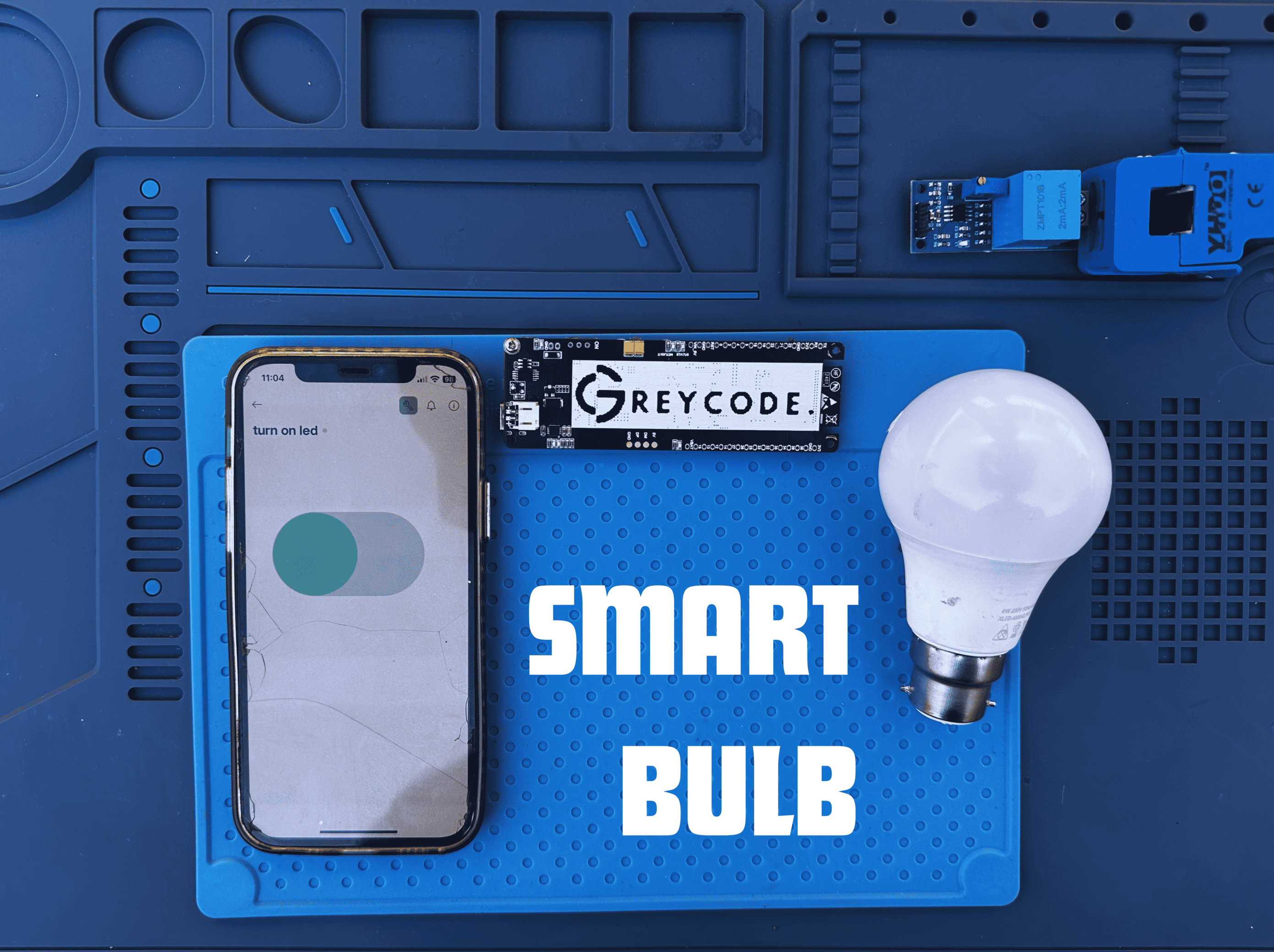
Smart Bulb
Greycode Team
02, June 2025
In this tutorial, you will learn how to control a standard AC bulb using the Greycode Board and a relay module. This is a foundational project in home automation, where microcontrollers like the Greycode Board can remotely control high-voltage appliances (like lights, fans, or sockets) using relays.
Components Needed
- Greycode IoT Dev Board
- Single-channel Relay Module
- AC Bulb + Holder
- 230V AC Power Source
- Jumper Wires
- C-type USB Cable
- Breadboard (Optional)
Additional Requirements
- BLYNK IoT Application
- Internet Connection
Part 1: Physical Connection
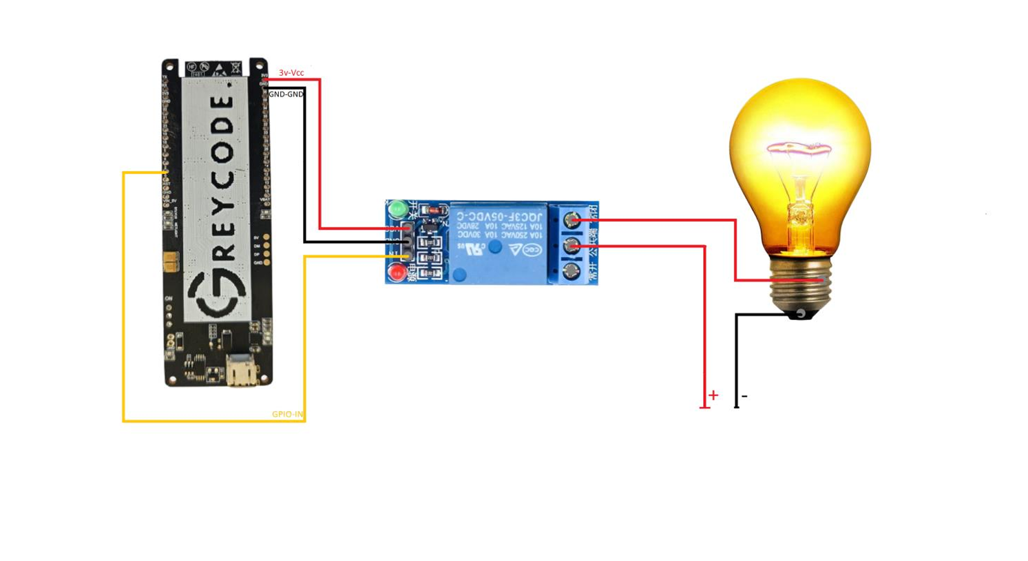
Relay Module Pins:
- IN - GPIO 26 (GREYCODE Board)
- VCC - 5V (GREYCODE Board)
- GND - GND (GREYCODE Board)
- COM - Live Wire From AC
- NO Live Wire To Bulb
Neutral wire goes directly to the bulb's other terminal
Circuit Diagram
Use the circuit diagram below as a connection reference.
Part 2: Setup Blynk App
Step 1: Blynk Setup
- Install the Blynk IoT app from the Play Store or App Store.
- Sign up and visit https://blynk.cloud.
-
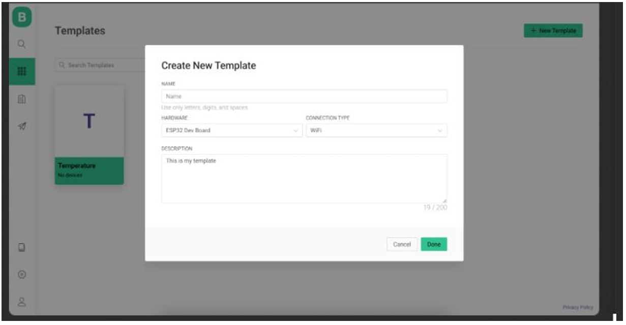
Create a new template:
- Name: LED Control
- Hardware: Greycode Dev Board
- Connection: Wi-Fi
-
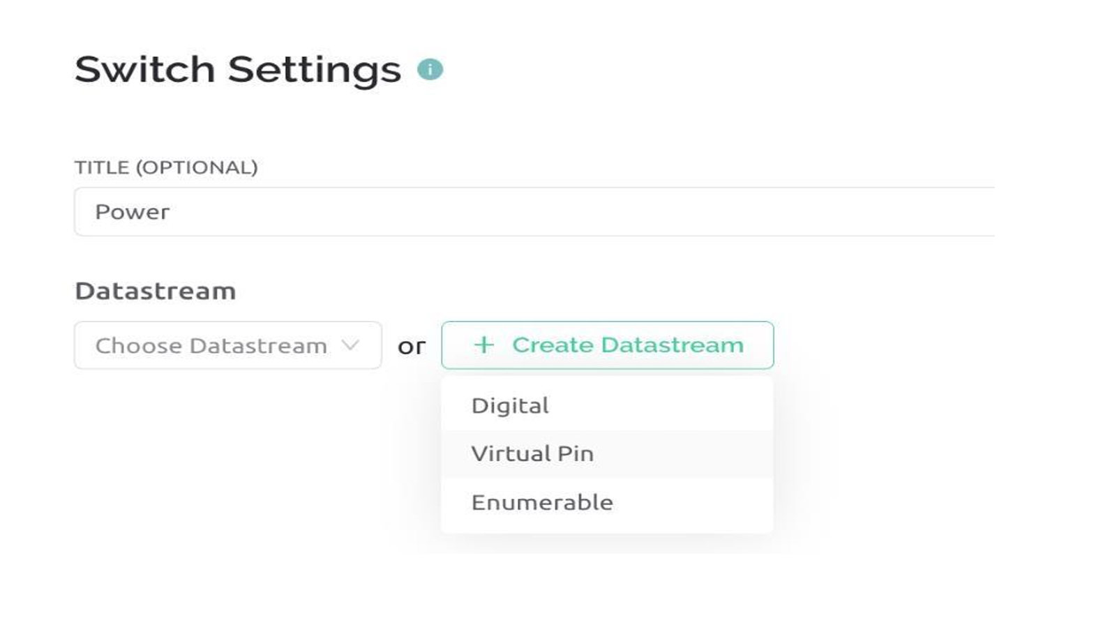
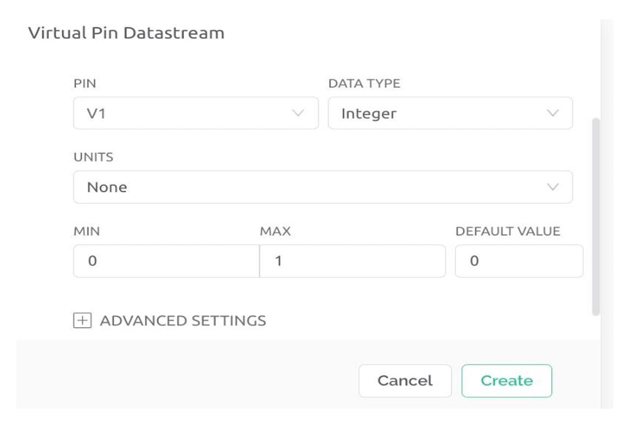
Create a Datastream:
- Type: Virtual Pin (V0)
- Data Type: Integer
- Min: 0
- Max: 1
- Save your template configuration.
-
Copy the following information:
- Template ID
- Device Name
- Auth Token
Step 2: Code Setup (Visual Studio / PlatformIO)
-
Create a new project:
- Name: BlynkLED
- Board: ESP32 Dev Module
- Framework: Arduino
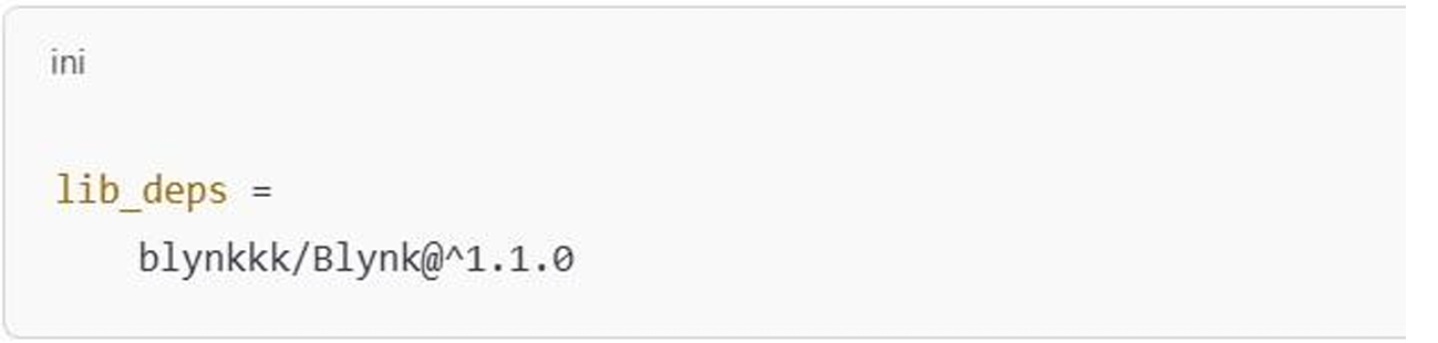
- Install the Blynk library (via Library Manager).
Main Code
#define BLYNK_TEMPLATE_ID "TMPL2RepqsLwr"
#define BLYNK_TEMPLATE_NAME "Blink LED/Bulb"
#define BLYNK_AUTH_TOKEN "6HlsOi4LFaPrH4vFrtVlsFy0HNMfcbXG"

#include <WiFi.h>
#include <BlynkSimpleEsp32.h>

#define RELAY_PIN 2

char auth[] = BLYNK_AUTH_TOKEN;
char ssid[] = "Peace C33";
char pass[] = "12345678";

BLYNK_WRITE(V0) {
  int state = param.asInt();
  digitalWrite(RELAY_PIN, state);
  Serial.println(state ? "Relay ON" : "Relay OFF");
}

void setup() {
  Serial.begin(115200);
  pinMode(RELAY_PIN, OUTPUT);
  digitalWrite(RELAY_PIN, LOW); // Relay is OFF by default
  Blynk.begin(auth, ssid, pass);
}

void loop() {
  Blynk.run();
}
Important: Make sure to replace the template ID, token, and Wi-Fi credentials with your own from Blynk.
Step 3: Upload and Monitor
- Connect your Greycode board via USB-C.
- Click Build (✓) then Upload (→).
- Open the Serial Monitor to confirm connection logs and relay status.
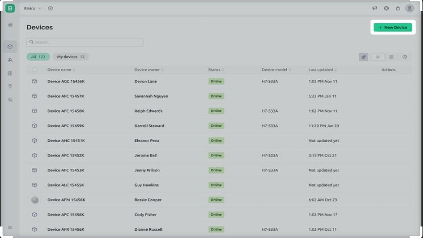
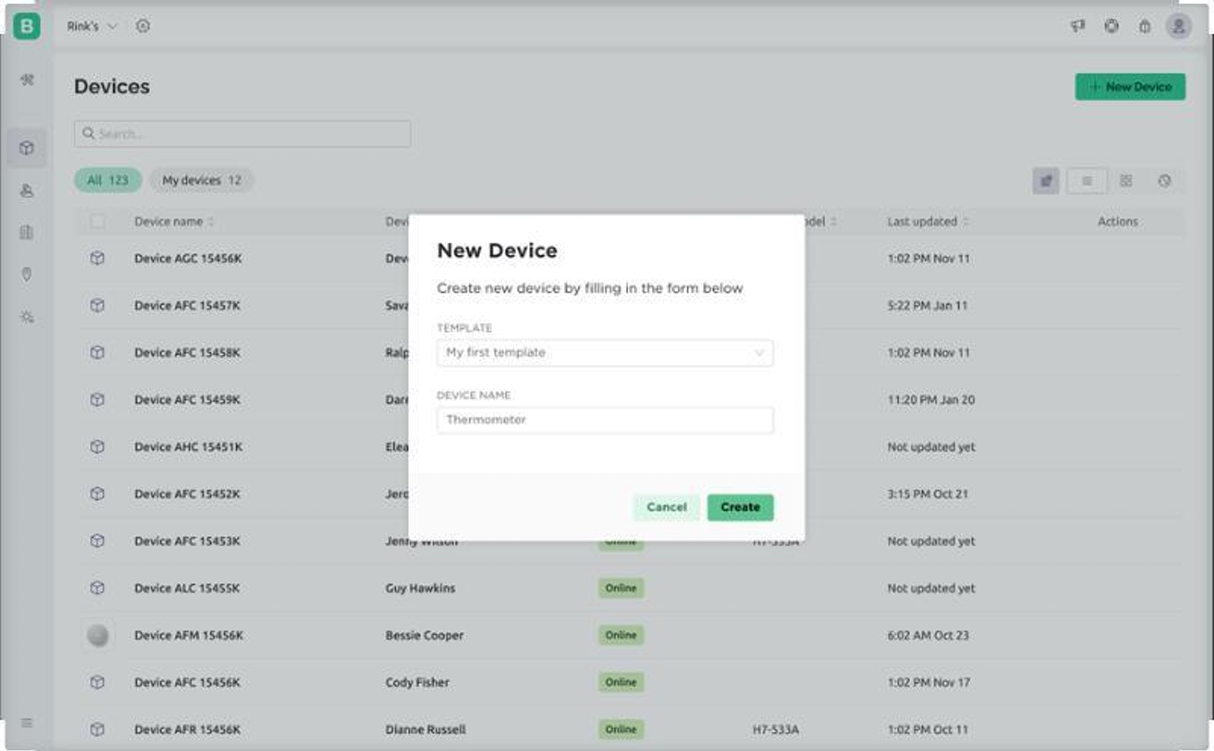
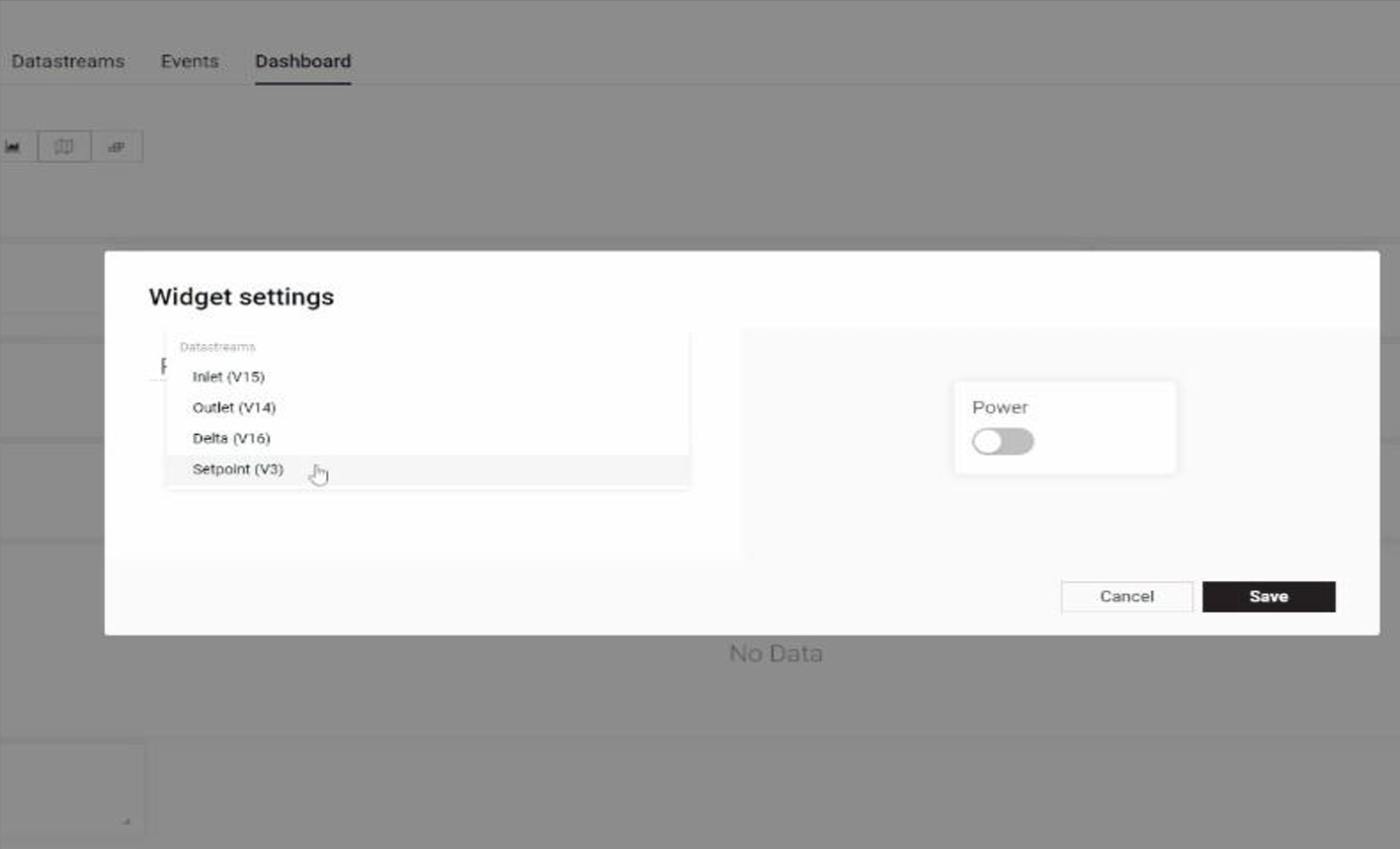
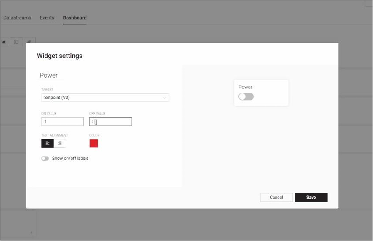
Step 4: Mobile App Setup
- Create a device in Blynk using your template.
- Add a Button widget and link it to V0.
- Set the mode to Switch.
Manual Testing
- You can modify the code to blink the bulb ON for 3 seconds, OFF for 3 seconds as a test.
- Using the Blynk app, toggle the button to turn the bulb ON/OFF instantly.
Conclusion
You've successfully created a smart bulb setup using the Greycode IoT Board and Blynk. With this knowledge, you can control any AC appliance, schedule routines, or even integrate voice control.
Next Challenge: Expand the project to control four bulbs independently!
Troubleshooting Tips
- No Wi-Fi connection? Check the code to see if Wi-Fi credentials are correct and ensure that your Wi-Fi is stable.
Start Your Own Project Now
- Click Here to watch the tutorial on Our Social Media Pages.
Leave a Comment
Comments (0)
Join the discussion
No comments yet. Be the first to share your thoughts!