Smoke Detector System Tutorial
Greycode Team
04, July 2025
In the depths of a mine, safety is everything. Even a small spark can turn into a deadly hazard if smoke goes undetected. With simple tools and a bit of code, we can build a smart smoke detection system that saves lives. In this project, we'll build a smoke detection alarm system using the Greycode IoT Dev Board microcontroller.
1. Components Needed
- Greycode IoT Dev Board
- MQ-2 Smoke Sensor
- I2C 16x2 LCD
- Active Buzzer
- LED Red
- 220 Ohms Resister
- Jumper Wire
- C-type USB Cable
- Breadboard (Optional)
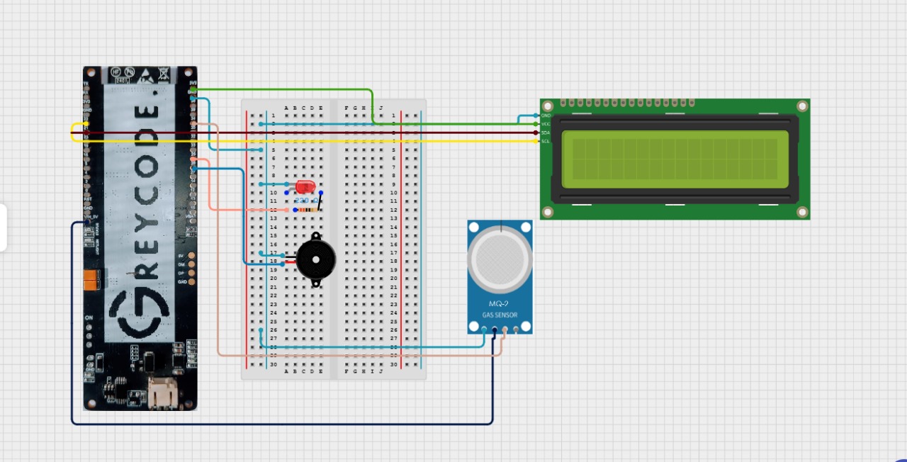
2. Circuit Diagram
Use the circuit diagram below as a connection reference.
3. Wiring Guide
MQ-2 Smoke Sensor:
- Analog Out - GPIO 34 (GREYCODE Board)
- VCC - 5V (GREYCODE Board)
- GND - GND (GREYCODE Board)
LED:
- Anode - GPIO 25 (GREYCODE Board), Connect via 220 Ohms Resistor
- Cathode - GND (GREYCODE Board)
Buzzer
- Positive - GPIO 26 (GREYCODE Board)
- Negative - GND (GREYCODE Board)
LCD
- SDA - GPIO 21 (GREYCODE Board)
- SCL - GPIO 22 (GREYCODE Board)
- VCC - 5V (GREYCODE Board)
- GND - GND (GREYCODE Board)
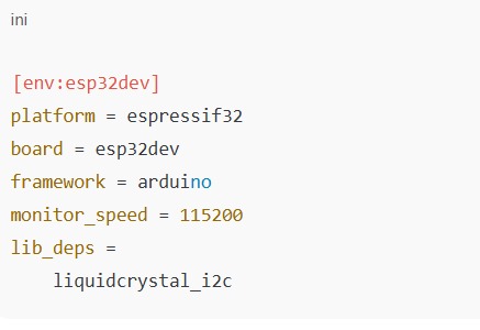
4. Creating a New Project in Visual Studio Code (PlatformIO)
To get started with coding your ESP32 smoke detector project, follow these steps in Visual Studio Code using the PlatformIO extension:
-
Open Visual Studio Code
- Launch VS Code from your desktop or start menu.
-
Open Platform IO Home
- On the left sidebar, click the PlatformIO alien icon (🐙) to open the PlatformIO Home menu.
-
Click "New Project"
- You'll see a welcome screen. Click the "New Project" button
-
Enter Project Details
- Name: Type your project name, e.g ESP32 Smoke Detector
- Board: In the drop-down list, select your ESP32 board (usually "ESP32 Dev Module" under the "espressif32" platform)
- Framework: Select Arduino
-
Click "Finish"
- PlatformIO will now generate a new project folder with all necessary files (like platformio.ini, main.cpp, etc.)
-
Waiting for Indexing
- VS Code might take a few seconds to install board support and index your libraries.
Once done, you're ready to start coding inside the src/main.cpp file.
5. Install Libraries
6. Find LCD I2C Address
Each I2C device (like the LCD) has a unique hexadecimal address that the ESP32 chip uses to talk to it (like a street address). But not all LCDs have the same address — some use 0x27, others 0x3F, etc.
To avoid communication issues, we scan for the correct address using a simple sketch. Run this sketch first to find your LCD's address.
#include <Arduino.h>
#include <Wire.h>

void setup() {
  // Initialize I2C communication on SDA = 21, SCL = 22
  Wire.begin(21, 22);

  // Start serial communication at 115200 baud
  Serial.begin(115200);
  Serial.println("I2C Scanner Initialized");
}

void loop() {
  byte error, address;

  Serial.println("Scanning for I2C devices...");

  // Loop through all possible I2C addresses
  for (address = 1; address < 127; address++) {
    Wire.beginTransmission(address);
    error = Wire.endTransmission();

    // If no error, a device responded at this address
    if (error == 0) {
      Serial.print("I2C device found at address 0x");
      Serial.println(address, HEX);
    }
  }

  delay(5000); // Optional: wait a second before next scan
}
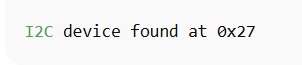
Look for something like:
7. Full Function Code
This section gives you a complete working code that you can upload directly to your ESP32. It reads data from the MQ-2 smoke sensor, checks if the smoke level is high, turns on the LED and buzzer if needed, and displays the sensor value on the LCD.
This code brings all the components (sensor, display, buzzer, LED) together into one functional system.
#include <Arduino.h>
#include <Wire.h>
#include <LiquidCrystal_I2C.h>

// Pin configuration
const int smokeSensorPin = 34;   // Analog input pin for smoke sensor
const int ledPin = 25;           // Digital output pin for LED
const int buzzerPin = 26;        // Digital output pin for buzzer

// Smoke threshold value
const int smokeThreshold = 400;  // Adjust based on your sensor's sensitivity

// Initialize LCD: address 0x27, 16 columns x 2 rows
LiquidCrystal_I2C lcd(0x27, 16, 2);

void setup() {
  // Initialize serial communication (optional for debugging)
  Serial.begin(9600);

  // Set pin modes
  pinMode(ledPin, OUTPUT);
  pinMode(buzzerPin, OUTPUT);

  // Initialize LCD
  lcd.init();
  lcd.backlight();
  lcd.setCursor(0, 0);
  lcd.print("Smoke Monitor");
  delay(2000);
  lcd.clear();
}

void loop() {
  // Read analog value from smoke sensor
  int smokeValue = analogRead(smokeSensorPin);

  // Print smoke value to Serial Monitor (for debugging)
  Serial.print("Smoke Value: ");
  Serial.println(smokeValue);

  // Display smoke value on LCD
  lcd.setCursor(0, 0);
  lcd.print("Smoke: ");
  lcd.print(smokeValue);
  lcd.print("    "); // Clear leftover characters

  // Check if smoke level exceeds threshold
  if (smokeValue > smokeThreshold) {
    digitalWrite(ledPin, HIGH);
    digitalWrite(buzzerPin, HIGH);
    lcd.setCursor(0, 1);
    lcd.print("!! Smoke Detected !!");
  } else {
    digitalWrite(ledPin, LOW);
    digitalWrite(buzzerPin, LOW);
    lcd.setCursor(0, 1);
    lcd.print("Status: Normal     ");
  }

  delay(500); // Delay for stability
}
8. Code Explanation
-
PinMode() and digitalWrite()
- We need to control hardware components (like the LED and buzzer) using ESP32.
- pinMode() sets the pin as an OUTPUT so it can send a voltage.
- digitalWrite() turns them ON (HIGH) or OFF (LOW) depending on smoke level.
-
analogRead(smokeSensorPin)
- The MQ-2 smoke sensor gives an analog voltage based on the amount of smoke it detects
- analogRead() reads this values (0-4095 on Greycode IoT Dev Board).
- Higher value = more smoke.
-
smokeThreshold
- We use this value to decide when to sound the alarm.
- If the smoke value is greater than 800 → it means the air might be smoky or polluted → trigger alarm.
- You can adjust this number based on real-life tests (calibration).
-
LCD (lcd.print(...))
- The LCD shows the real-time smoke value so the user can see how much smoke is present.
- This is helpful even if the alarm isn't triggered — it provides feedback
- We keep it simple: only showing the number, not words like "DANGER".
-
delay(500)
- Waits half a second between readings
- This avoids flickering or spamming the screen too quickly
9. Upload the Code
- Plug Greycode IoT Dev Board into USB
- Click PlatformIO: Upload (checkmark icon)
10. Calibrating Threshold
- Run the code
- Note readings in clean air (~300)
- Expose sensor to smoke (~1200)
- Set threshold slightly above clean-air value (~800)
11. Troubleshooting LCD
- Blank display → check I2C address
- Garbage characters → adjust contrast (potentiometer on I2C backpack)
- No output → check connections (SDA/SCL)
Leave a Comment
Comments (0)
Join the discussion
No comments yet. Be the first to share your thoughts!